
Categories
- Our Blog (243)
- Technology Support (23)
- Tools Published (0)

Structure description
1. Slider part: hydraulic transmission is adopted, and the slider part is composed of a slider, an oil cylinder and a fine-tuning structure of a mechanical stopper. The left and right oil cylinders are fixed on the frame, the piston (rod) drives the slider to move up and down through hydraulic pressure, and the mechanical stop is controlled by the numerical control system to adjust the value;
2. Workbench part: controlled by the button box, the motor drives the stopper to move back and forth, and the moving distance is controlled by the numerical control system. The minimum reading is 0.01 mm (the front and rear positions have travel switch limits);
3. Synchronization system: The machine consists of a mechanical synchronization mechanism composed of torsion shafts, swing arms, joint bearings, etc., with simple structure, stable and reliable performance, and high synchronization accuracy. The mechanical stop is adjusted by the motor, and the numerical control system controls the value;
4. Stopper mechanism: The stopper is driven by a motor, and the two screw rods are driven to move synchronously through a chain operation. The numerical control system controls the size of the stopper.
Structural features
1. Adopt all-steel welded structure, with sufficient strength and rigidity;
2. Hydraulic drive, the cylinders at both ends of the machine tool are placed on the sliding block to directly drive the sliding work;
3. The slider synchronization mechanism adopts torsion shaft for forced synchronization;
4. Using mechanical block structure, stable and reliable;
5. The stroke of the slider can be adjusted quickly by motor, fine-tuned manually, and the counter is displayed;
6. Oblique wedge-type deflection compensation mechanism to ensure higher bending accuracy.
 On the importance of human resources for intelligent manufacturing of sheet metal
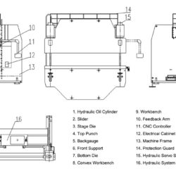 High-precision CNC bending machine maintenance and working condition
 CNC Press Brake failure how to do
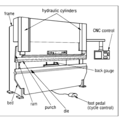 Large double machine linkage CNC Press Brake technology
 Precautions for the use of hydraulic shearing machine